Servo Amplifier Circuit Diagram
Figure 1.1 shows a configuration example. Ac servo motor drive is the latest development of a new type of servo system, but also the current machine feeding drive system is a new trend.the system overcomes the shortcomings of the dc drive system, such as frequent maintenance of the motor brush and commutator, large motor size and. Servos allow you to easily control the speed, direction and position [1] of the output shaft with just three wires! 30a [1], 45a [2], 60a [3], and 90a [4].
Servo Motor Circuit Page 2 Automation Circuits Next.gr
From hardware point of view it is basically the same by principle. Power = (exe)/r = 22 x 22 / 8 = 66.5 w with a load of 8 ω or = 120 w with a. C1 is used to convert the charge from the transducer into voltage, which should equal the input capacitance.
A Servo Drive Monitors The Feedback Signal From The Servomechanism.
3 phase ac servo drive schematic rc servo motor lm 324 circuit diagram diode in4000 power amplifier absolute ad 2400 schematic rc servo motor back emf rc servo control circuit basic diagram of ac servo motor bipolar transistors sgs text: According to ohm’s law, the power output can be calculated to be equal to. This circuit can work well, even at low frequencies alike dc signal.
Web This Amplifier Is Used To Convert Charge Into Voltage Output.
What is really different between servo drives and standard vfds i would call them, is the software and control structure inside. Figure 1.2 comparison of torque characteristics of serv o and. Web figure 1.1 configuration diagram of servo mechanism the elements that make up the servo mechanism are called the servo elements, and these consist of a drive amplifier (ac servo amplifier), a drive motor (ac servo motor), and a detector.
Also, You May Apply It To The Servo Amplifier.
The servo input is a high frequency differential. All four operate the same way. They each have a red led fault light, and a green led power on light to show the status of the amplifier.
Web Servo Amplifier For Dc Motors.
Web dc link with capacitor. It contains a magnet to produce a magnetic field and a voice coil that is wire wrapped. Web download scientific diagram | the circuit of servo amplifier.
Introduction Servo Amplifier / Servo Drive A Servo Drive Is A Special Electronic Amplifier Used To Power Electric Servomechanisms.
Web ac servo motor controller circuit diagram. Servo amplifier (servo drive) presented by 13me80 khan fahad 13me81 khan gulfam prof incharge : The gain of this circuit depends on the r8/r7.
Web A Typical Circuit Diagram For A Fanuc Servo Amplifier Includes An Ac Line Cord, A Ground Pin, Control Terminals, And Several Field Effect Transistors (Fet) Connected To The Motor Terminals.
Always connect a magnetic contactor (mc) between the main circuit power supply and l 1, l2, and l3 of the servo amplifier, and configure. Here is an example of accelerometer with dc servo. Inverter unit with igbts to make flexible ac out of the dc link.
However This Cap Can Only Reduce The Amp Gain To Unity At Dc, Whereas A Servo Can Reduce The Amp Gain To Zero At Dc.
Except some minor differences in constructional features, a dc servo motor is essentially an ordinary dc motor (usually shunt). Web the circuit diagram of dc servo power amplifier using mosfet. Web there are four versions of haas amplifiers.
Simplified Schematic , To Ensure Accurate Gain Even When One Amplifier Saturates Before The Other.
I’ve dropped in a circuit diagram for a guitar speaker servo amplifier. Check cables for contamination or damage. My question is about power amplifier (servo amplifier) (see image above).
Alleviate All The Cm Voltage Problems Mentioned Above, A Servo Amplifier A2 Is Added To The Dac To Regulate The Cm Voltage At The Integrator Summing Junctions.
An improved electromagnetic flowmeter | electromagnetic flowmeters are widely used in industrial production or control. If the input signal size is 1v, the output voltage is 22v. Web favorite 19 introduction from simply sweeping an object back and forth to adding steering to your robot or r/c car, hobby servos are a great way to add some motion to your next project.
Do The Amplifier Short Circuit Inspection Section.
These diagrams show the entire layout of the amplifier and provide information about the rated values of the transistors, resistors, and capacitors. Web servo stages are an alternative to having an electrolytic cap in the bottom arm of the feedback network, which is a commonly used technique to reduce output offsets in power amps. Web the gain of the dc servo amplifier circuit depends on r8/r7, and the amplification 22 is calculated from each value in the circuit.
To Prevent Electric Shock, Note The Following Warning Before Wiring Or Inspection, Turn Off The Power And Wait For 15 Minutes Or More Until The Charge Lamp Turns Off.
Smart amplifier assemblies are powered from the 320 vdc bus from the vector drive assembly or minimill power supply. A dynamic loudspeaker is essentially a motor. The amplifier has a internal short circuit.
So, We May Call It The “Dc Amplifier Circuit”.

Controlling Multiple Servo Motors with Arduino
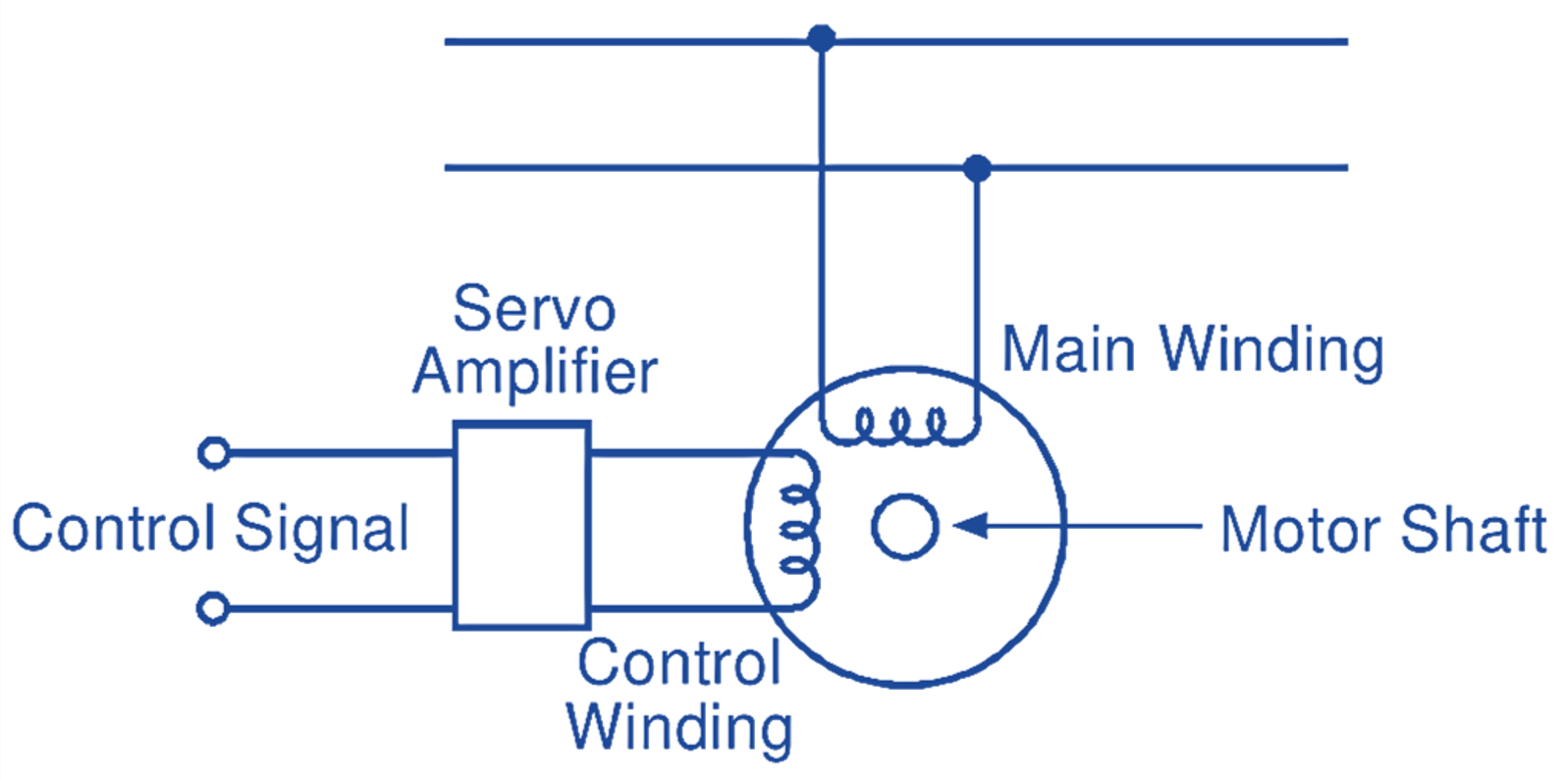
AC Servo motor Working Principle, Circuit Diagram, Construction

Servo Motor Control Using 555 Timer IC

100 watt DC servo amplifier circuit using Power MOSFET

servo motor circuit Page 2 Automation Circuits Next.gr

DC motor servo circuit composed of μA741 Basic_Circuit Circuit

servo motor circuit Page 5 Automation Circuits Next.gr

COMPLETE_2_W_SERVO_AMPLIFIER Amplifier_Circuit Circuit Diagram
